Athabasca University | AU Student/Staff Login | Invited Guest Login
All Site Activity
- Susanne Cardwell commented on the blog Combobulating Continuity via Connectors and Conductors September 28, 2017 - 1:16pmHi Tyler. Great robot. What actuator did you use to get the arm joint to work ... and how did you attach it? I went to a place called Fastenall in the Southeast and they knew as much as I did about how to make a robotic arm joint move....
- Tyler Lucas published a blog post Combobulating Continuity via Connectors and Conductors September 28, 2017 - 12:08pmComments
- Tyler Lucas September 28, 2017 - 1:56pm
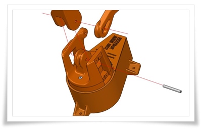
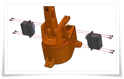
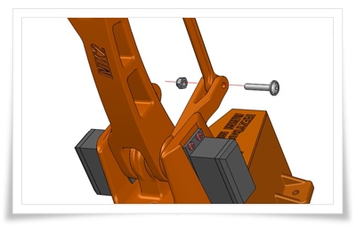
This arm isn't the easiest to explain. It's based on Carlo Franciscone's EEZYbotARM MK2, modified to have more complex connections in that my version has different size ball-bearings in nearly every joint. I'll show you some of Carlo's great assembly photos from his website:


They're really just plain M3 and M3 bolts with lock nuts (nylon). I'd recommend at least a pair of washers in between the moving parts to reduce friction, and don't tighten the nut very much -- this is where the locking mechanism of the nut comes in handy, as a regular nut needs to be tightened against something or it will loosen off. I used a Power HD-1501MG and a MG946R servo and aluminum horns with M2 bolts/screws to lift the two parts of the arm.
If your arm doesn't need to lift much, don't use a bolt or anything else to support it, just attach the arm directly to the servo. The SparkFun Inventor's Kit (SIK) comes with a small servo: the "Micro Servo A0090" or "ROB-09065" or "SG90", similar to the popular Hitec HS-55. It comes with a bunch of white plastic horns. These attach to the servo output and can be screwed directly onto an arm, et voila. This is exactly what I did for my Shoddy Robotic Arm. (I actually used sticky tack to keep it together, but I don't recommend that.)
Here's the STEP file for my robot arm: [link]. It's a bit different from Carlo's MK2, and is not complete, but it shows the connections/joints clearly.
- Susanne Cardwell September 28, 2017 - 4:42pm
Nice reply. Thanks Tyler. Nice wiring on your robot too. The wires look cosmetic. Who'd ever guess something so visually nice would be primarily functional.
What program did you use to 3d print your robot? Did you measure the servos for your 3d print job?
Lastly, are there 2 servos for the sake of balance or do they kind of work like wheels? I believe that you spin one wheel faster than the other to get them to turn. Is that correct? Thank you.
- Tyler Lucas September 28, 2017 - 5:01pm
I use Autodesk Fusion 360 for 3D design, Simplify3D to slice models, and Octoprint (OctoPi on RPi2) to feed the printer with data. Any decent 3D design program can open that STEP file. I did measure the servos -- there is always a lot of measuring going on when designing connecting parts... The two servos you see in the photos above move two different parts of the arm. Mataric covers servos under 4.3.3 Servo Motors (p. 37...).
- Blogs have evolved a bit over the past 20 years or so, and diversified. The always terrific Ben Werdmuller here makes the distinction between thinkpieces (what I tend to think of as vaguely equivalent to keynote presentations at a conference, less...
- Daniel Wilton uploaded the file CIDER Session slides October 2017 in the group Canadian Initiative for Distance Education Research - CIDER September 27, 2017 - 11:12am
- Jon Dron bookmarked Instagram uses 'I will rape you' post as Facebook ad in latest algorithm mishap September 26, 2017 - 4:45pmAnother in a long line of algorithm fails from the Facebook stable, this time from Instagram... This is a postcard from our future when AI and robots rule the planet. Intelligence without wisdom is a very dangerous thing. See my recent post on...
- Anonymous commented on the blog Strategies for successful learning at AU September 25, 2017 - 9:50amGreat post, Jon. Yes, challenge is necessary for learning and we always worries those students who feel it too difficult. Students can always ask for help but many don't even struggling fruitlessly, and those students are really at the risk of...
- Jon Dron bookmarked Infants make more attempts to achieve a goal when they see adults persist September 24, 2017 - 8:03pmA straightforward and briefly reported study that supports the rather obvious hypothesis that quite young (15-month-old) children can and do learn from observing adults, at least in the short term. The twist here is that adults in the study were...
- Tyler, I just finished the book "Life 3.0 Being Human in the Age of Artificial Intelligence" by Max Tergmark (MIT). Extremely fascinating look at the questions humanity will need to deal with (now) if we are to have any measure of control over the...
- Gerald Ardito commented on a bookmark Amazon helps and teaches bomb makers September 23, 2017 - 1:43pmJon, I think that recommender systems can be good (and I know yours were/are). I was responding to the corporate instantiations in education in particular. Mike Caulfield had a nice piece about Netflix recommender engines not really...
- As in all things, it ain't what you do, it's the way that you do it. Having worked on recommender systems, especially adaptive ones, for my PhD and for some years afterwards, I do see that there are many ways they can have a place. But there are...
- Gerald Ardito commented on a bookmark Amazon helps and teaches bomb makers September 23, 2017 - 12:33pmJon, I agree with the points you are raising here. There is a pervsuasive (and generally inaccurate) notion that learning is the acquisition of simple sets of skills. We seem to believe that out of that acquisition of skill sets that higher order...
- Richard Huntrods commented on the blog Project Proposal: Automatic Object Relocation September 22, 2017 - 10:43amGreat idea Tyler! One thought on the weight of the effector when fully extended - perhaps see if you can design some type of counterweight to balance things when fully extended?
- Daniel Wilton uploaded the file CIDER Session Oct 2017 recording in the group Canadian Initiative for Distance Education Research - CIDER September 22, 2017 - 1:35am
- Daniel Wilton uploaded the file CIDER Session Oct 2017 upcoming in the group Canadian Initiative for Distance Education Research - CIDER September 22, 2017 - 1:34am
- Daniel Wilton uploaded the file CIDER Session Oct 2017 banner in the group Canadian Initiative for Distance Education Research - CIDER September 22, 2017 - 1:33am
- Daniel Wilton uploaded the file CIDER Session Oct 2017 thumbnail in the group Canadian Initiative for Distance Education Research - CIDER September 22, 2017 - 1:32am
- It's a damning indictment of our collective resistance to truth that the point of this article still has to be restated, yet again. Amazingly, 93% of the general public and 76% of educators still erroneously believe that we should be taught in ways...
- Susanne Cardwell commented on the blog Project Proposal: Automatic Object Relocation September 21, 2017 - 5:13pmGreat feedback, thanks. I needed to look up axle, but now I get the gist. I wonder if I could take the axle from servo motor and attach it to a bracket that attaches to an arm. Thanks very much.
- Tyler Lucas commented on the blog Project Proposal: Automatic Object Relocation September 21, 2017 - 4:46pmHey Susanne. Most of the joints in this arm have ball bearings, but that's not really required if you're not worried about friction. For small loads you can just attach an arm directly to a motor, servo, or stepper, without giving it additional...
- Susanne Cardwell commented on the blog Project Proposal: Automatic Object Relocation September 21, 2017 - 4:11pmGreat robot, Tyler, and thanks for all your feedback. Would you please tip me off on how to make an arm joint? What bolt or whatever would allow for the rotation? Thank you
Help
The activity pages show you all the posts that you are allowed to see on the site. This is sometimes referred to as the activity stream or river. It is a great way to keep up to date with what has been posted on the site. You can configure the river to show things that particularly interest you - in your settings you can configure activity tabs to display activities from people in specific groups and your circles.
Adding comments to this site
We welcome comments on public posts from members of the public. Please note, however, that all comments made on public posts must be moderated by their owners before they become visible on the site. The owner of the post (and no one else) has to do that.
If you want the full range of features and you have a login ID, log in using the links at the top of the page or at https://landing.athabascau.ca/login (logins are secure and encrypted)
Disclaimer
Posts made here are the responsibility of their owners and may not reflect the views of Athabasca University.


 Loading