Athabasca University | AU Student/Staff Login | Invited Guest Login

Assignment 2 Weblog

Chapter readings and Notes
Grasping at Straws
Inverse kinematics and dynamics-related problems require complicated computations to be solved, which makes robotic manipulation a challenging task. The effectiveness and performance of robotic systems are substantially impacted by these computational difficulties.
In the field of robotic manipulation, inverse kinematics is a key factor in understanding how to precisely place a robotic manipulator's end-effector, which might be a gripper or a tool, at a particular point. Complex calculations must be performed during this procedure to take into account the angles of each component inside the manipulator.
In the context of robotics, dynamics refers to the complex interaction between an object's motion and its energy characteristics. To achieve accurate and controlled robotic manipulation, it is crucial to comprehend and manage these dynamics.
Complexity of Computation:The computations required for both inverse kinematics and dynamics are computationally expensive. These calculations demand substantial computational resources, which can slow down the execution of tasks and hinder real-time responsiveness.
Joint Limitations: Robotic manipulators are composed of joints that facilitate movement. However, these joints have inherent limitations in terms of their range and modes of movement. Two common joint types include ball-and-socket joints, which allow for rotational movement along fixed axes, and prismatic joints, which enable linear, piston-like motion. These joint limitations must be considered during planning and execution to prevent undesirable outcomes.
Collision Avoidance: In the process of manipulation, robots must navigate their environment while avoiding collisions with obstacles and their own physical structure. This adds an additional layer of complexity to the task, as the robot needs to make real-time decisions to ensure safety and task completion.
Food for Thought
1. How many DOF are there in the human hand? Can you control each of them independently?
There are 27 degrees of freedom (DOF) in the human hand. Not all of these DOF can, however, be independently controlled. Many of them are synchronized, enabling intricate and exact actions like grasping and object manipulation. Since the hand has several DOF, they frequently cooperate as opposed to being controlled separately.
2. Which of the two joint types we discussed, rotational and prismatic, is more commonly found in biological bodies? Can you think of specific animals?
Joints with rotational motion are more frequent in biological bodies. They are common in many animals, including people. The elbow and knee joints in humans are two examples of rotating joints. For diverse actions including walking and gripping objects, these joints provide flexion and extension movements. In comparison to rotational joints, prismatic joints, which allow for linear motion, are less frequent in biological organisms.
3. Are astronaut suits exoskeletons? What about a lever-controlled backhoe?
Astronaut suits can be considered a type of exoskeleton.They are made to protect and sustain astronauts while they labor in the harsh temperatures and vacuum of space. With improved mobility thanks to these suits, astronauts can move around and carry out activities in the demanding environment of space. Exoskeletons, which in the case of astronaut suits are external wearing structures, support and enhance the user's movements.
On the other hand, a digger with a lever control is not commonly thought of as having an exoskeleton. A digger is a large piece of equipment for excavation and digging. Although its numerous components can be operated by levers and controls, it is not worn by the user to improve their physical skills. Typically, exoskeletons are made to be worn by a person to assist with tasks like lifting heavy objects or providing support and mobility, whereas a backhoe is a separate machine operated by a user from the outside.
4. Imagine an exoskeleton which has its own sensors, makes its own decisions, and acts on them. This is definitely a robot, yet it is controlled by a human and attached to the human’s body. Can you imagine where this could be useful?
An exoskeleton with its own sensors, decision-making capabilities, and the ability to act on those decisions, while still being controlled by a human, could find utility in various applications:
-
Medical Rehabilitation: Such an exoskeleton could assist individuals with mobility impairments or those recovering from injuries. The exoskeleton's sensors could detect the user's movements and body position, making real-time adjustments to provide support and stability. It could also adapt to the user's gait and balance, aiding in physical therapy and rehabilitation.
-
Industrial Work: In industrial settings, workers often need to lift heavy objects or perform repetitive tasks that can lead to physical strain and injuries. An intelligent exoskeleton could reduce the risk of injuries by providing assistance and support during these tasks.
-
Military: Soldiers carrying heavy loads over long distances could benefit from exoskeletons that adapt to the terrain and adjust the distribution of weight, reducing fatigue and increasing endurance.
-
Search and Rescue: Exoskeletons equipped with sensors and decision-making capabilities could be used by search and rescue teams in disaster-stricken areas. They could assist in navigating through debris, lifting heavy objects, and providing stability in unstable environments.
-
Aging Population: With an aging population, exoskeletons that enhance mobility and support daily activities could improve the quality of life for older adults. The intelligent exoskeleton could anticipate movements and provide assistance in real-time.
-
Sports and Athletics: Athletes and sports enthusiasts may use exoskeletons during training to enhance performance and reduce the risk of injuries. These exoskeletons could adapt to different training scenarios and provide feedback on form and technique.
-
Space Exploration: Astronauts conducting extravehicular activities in space could benefit from intelligent exoskeletons that adapt to the unique challenges of moving in microgravity environments.
5. Robotic dogs have been used to play soccer. Because they are not designed for that task, they move slowly and have trouble aiming and kicking the ball (not to mention finding it, but that’s not part of manipulation; it belongs to sensing, discussed in the next few chapters). Some of the best robot soccer teams have come up with a clever idea: instead of having the dogs walk as they normally do, they lower them so that the two rear legs are on the ground, used to grasp the ball and kick it, which is much easier. This turns out to work very well, even if it looks rather silly. What are the end-effectors of the dogs in that case? Are the dogs now purely mobile robots?
In this case, the robotic dogs' two hind legs serve as end-effectors. These legs efficiently perform as manipulators for the football task by grabbing the ball and kicking it.
-
The robotic dogs' capacity to handle and interact with the football with their back legs, despite being predominantly mobile robots, blurs the distinction between mobile robots and manipulator robots. They show traits of both in this particular situation:
-
Mobile Robots: The robotic canines are still able to roam around the football pitch, although they are somewhat slower and less agile than robots specifically made for the sport. Their main job is to move around and take up positions in the game.
-
Robot manipulators: Using their back legs to grasp and kick the ball, the robotic dogs demonstrate a level of manipulation capability. Manipulators are typically robotic arms or limbs designed for precise control and interaction with objects, which aligns with what the dogs are doing when playing soccer.
What’s Going on?
Perception is a key element in the field of robotics for comprehending the world. The proprioceptive and exteroceptive sensor types are highlighted as this chapter explores the many facets of perception. Exteroceptive sensors are designed to perceive the outside world, whereas proprioceptive sensors concentrate on detecting the inside state of the robot. These sensors can be classified as contact, distance, light, sound, strain, rotation, acceleration, magnetic, smell, temperature, inclination, pressure, and altitude sensors, among many more types.
The perceptual system of a robot, however, faces intrinsic difficulties. There is a lot of uncertainty because of things like sensor noise, errors, constraints, effector and actuator noise, hidden states, and changing environmental conditions. Since there is inherent uncertainty in the world, it is difficult to calculate with exact accuracy. Additionally, there is an imbalance between the knowledge available to the robot and the knowledge it possesses, further contributing to uncertainty.
To address these challenges, robots engage in complex computations to distinguish relevant signal information from environmental noise and construct meaningful symbols. Four distinct types of perception are explored:
-
Action-oriented perception: Robots actively seek stimuli in the environment and respond accordingly.
-
Expectation-oriented perception: The robot utilizes its understanding of the environment to guide and constrain the interpretation of sensor data.
-
Task-driven attention: Sensors are strategically moved to sense in directions where crucial information is most needed or readily available.
-
Perceptual classes: The robot categorizes the world into manageable partitions, simplifying the perception process.
Food for Thought
1. Uncertainty is not much of a problem in computer simulations, which is why simulated robots are not very close to the real, physical ones. Can you figure out why?
There are a number of important reasons why computer models of robots exhibit less uncertainty than actual robots:
In a computer simulation, every variable and piece of information is perfectly specified and known. As is the case in the actual world, there is no inherent noise, mistakes, or sensor limitations that generate uncertainty.
-
settings that Can Be Idealised: Simulated settings can be made to be ideal and free of unforeseen external influences or disturbances. Real-world surroundings, on the other hand, are dynamic and frequently unpredictable, which greatly increases uncertainty.
-
Deterministic Physics: Deterministic physics engines are generally used in simulations, where the rules governing the virtual world are well-defined and predictable. Real-world physics involves intricate dynamics that are difficult to accurately model.
-
Data generation: Simulated robots generate data with high precision, without the inherent noise and inaccuracies present in physical sensors. This eliminates one major source of uncertainty in decision-making.
-
Computational Resources: Simulations can leverage vast computational resources to perform calculations with high accuracy and minimal computational noise. Physical robots often operate with limited onboard computational power.
-
Simplified Models: Simulated robots may use simplified or idealized models of sensors, actuators, and mechanics, which do not capture the full complexity and variability of real-world counterparts.
-
Lack of External Factors: Simulations typically do not account for external factors like weather conditions, wear and tear, or interactions with other real-world entities, all of which contribute to uncertainty in the physical realm.
2. Some robotics engineers have argued that sensors are the main limiting factor in robot intelligence: if only we had more, smaller, and better sensors, we could have all kinds of amazing robots. Do you believe that is all that’s missing? (Hint: if that were so, wouldn’t this book be much thinner?
No, improved robot intelligence cannot solely be attained by having more, smaller, and better sensors. Even though sensors are important, establishing robot intelligence also requires other complexity, including sensor integration, processing capacity, sophisticated algorithms, artificial intelligence (AI), physical mechanics, environmental comprehension, ethical considerations, and practicality. The field is multidisciplinary and calls for advancements beyond sensor technology alone.
3. Being able to sense the self, being self-aware, is the foundation for consciousness. Scientists today still argue about what animals are conscious, and how that relates to their intelligence, because consciousness is a necessary part of higher intelligence of the kind people have. What do you think it will take to get robots to be self-aware and highly intelligent? And if some day they are both, what will their intelligence be like, similar to ours or completely different?
Robot self-awareness and high intelligence are hard and contentious issues. It will likely take improvements in a number of areas to develop robots self-aware and extremely intelligent:
Developing AI systems that can handle enormous amounts of data and interpret it in a way that represents self-awareness is the goal of advanced AI and machine learning. This entails developing algorithms that can comprehend and gain knowledge from their own deeds and experiences.
-
Sensor Technology: Improving sensors to give robots a deeper comprehension of their surroundings and the capacity to recognise themselves there.
-
Memory and Experience: In order to learn from mistakes and evolve over time, robots would require a type of memory that stores previous experiences and encounters.
-
Ethical Considerations: Addressing moral dilemmas regarding robot consciousness and rights, as well as how to ensure responsible use of self-aware AI.
-
Interdisciplinary Research: Collaborations between experts in robotics, neuroscience, philosophy, and AI to gain a deeper understanding of consciousness and how it can be replicated in machines.
Simple Sensors: Switch on the Light
Sensor Categories: Sensors are categorized into passive and active types. Passive sensors detect physical properties in the environment and include detectors. Active sensors emit a signal and measure its interaction with the environment using emitters and detectors.
-
Switch Sensors: Simple passive sensors like switches allow or interrupt current flow, resulting in binary sensing (on/off). They serve as contact sensors, limit sensors, and shaft encoders.
-
Light as a Sensing Medium: Light is commonly used in sensors due to its versatile properties, including variable intensity, diverse wavelengths in a continuous beam, and the ability to be pulsed for modulation.
-
Reflected Light Sensors: These sensors measure resistance levels of reflected light. The resistance varies based on factors such as light intensity, differential intensity, and beam continuity. They detect object presence or absence.
-
Polarized Light: Polarized light travels in a specific direction along a particular plane. Filters can be used to eliminate unwanted wavelengths before detection.
-
Reflective Optosensors: Reflective optosensors come in two main types. Reflectance sensors use side-by-side emitters and detectors to detect object presence by measuring reflected light. Break beam sensors consist of an emitter and a detector facing each other, detecting beam interruption.
-
Resistive Position Sensors: Resistive position sensors, like potentiometers, take the form of knobs and sliders. They change resistance levels as the knob or slider is adjusted, enabling position or displacement measurement.
Food for thought
1. Why might you prefer a passive to an active sensor?
Simplicity: Passive sensors are typically simpler in design and construction, making them more cost-effective and easier to implement.
Lower Power Consumption: Passive sensors do not require an external power source to generate a signal, which can lead to lower power consumption. This is particularly important in battery-powered or energy-efficient applications.
Durability: Passive sensors are often more robust and durable because they lack active components that may be prone to wear and tear over time.
Less Complexity: Passive sensors can be less complex to integrate into a system since they don't involve emitting signals, which can simplify installation and maintenance.
Cost-Effectiveness: Passive sensors are generally more cost-effective, making them suitable for applications where cost is a primary concern.
Safety: In some situations, passive sensors may be safer to use because they don't emit signals that could interfere with other equipment or pose health risks.
Compatibility: Passive sensors may be compatible with existing systems and infrastructure, reducing the need for significant modifications.
2. Are potentiometers active or passive sensors?
Passive sensors include potentiometers. They fall under the category of passive sensors because they do not emit any external signals while measuring an environmental physical characteristic (in this case, the position of a knob or slider). When a knob or slider is moved, a potentiometer's resistance level changes, making it possible to measure a location throughout its range. Potentiometers are regarded as passive sensors because they don't actively emit signals to sense their surroundings.
3. Our stomach muscles have stretch receptors, which let our brains know how stretched our stomach is and keeps us from eating endlessly. What robot sensors would you say are most similar to such stretch receptors? Are they similar in form (mechanism of how they detect) or function (what they detect)? Why might stretch receptors be useful to robots, even without stomachs and eating?
Stretch receptors in the human body are similar to several strain sensors found in robots in terms of how they work. Despite their potential differences in shape, both gauge a material's deformation or stretching. Robotic strain sensors, such as resistive strain gauges or piezoelectric sensors, are useful for detecting collisions, monitoring the environment, manipulating objects, and providing feedback to the body. Although robots lack stomachs, these sensors still aid in their navigation, interaction with objects, and safe operation in a variety of situations.
Complex Sensors: Sonars, Lasers, and Cameras
Complex sensors provide rich data but require advanced processing.
Ultrasound, often used in sonar systems, utilizes sound frequencies beyond human hearing for echolocation. It involves an emitter and detector to bounce sound off objects and determine their locations. Specular reflection, where sound waves bounce off surfaces, can lead to inaccuracies, but techniques like using phased arrays or adjusting sensor angles can improve readings.
Lasers emit coherent radiation and combat specular reflection. They offer high accuracy but may be less precise at short distances due to the speed of light.
Cameras, akin to biological eyes, capture scattered light through a lens and an image plane. Image processing involves edge detection, noise reduction, and object segmentation. Various vision approaches, such as model-based, motion-based, stereo, and texture-based, are employed to understand the environment.
Biological vision combines these techniques, providing a comprehensive perception system. In contrast, robot vision focuses on efficiently identifying important information, often using color, reduced image planes, and additional sensors while considering the environment's knowledge.
Food for Thought
1. What is the speed of sound in metric units?
The speed of sound is roughly 343 meters per second (m/s) or 1235 kilometers per hour (km/h) in metric units in dry air at sea level and at a temperature of 20 degrees Celsius (68 degrees Fahrenheit). However, variables like temperature, humidity, and altitude can affect the speed of sound.
2. How much greater is the speed of light than the speed of sound? What does this tell you about sensors that use one or the other?
In a vacuum, light travels at a speed of around 299,792,458 meters per second (or 299,792 kilometers per second). In contrast, sound travels at around 343 meters per second in dry air at ambient temperature (about 20 degrees Celsius).
Because of this, the speed of light is far faster than the speed of sound. In dry air at room temperature, it travels at a speed that is around 874,030 times faster than the speed of sound
Important repercussions result from this speed discrepancy for sensors that rely on light or sound
Light-Based Sensors (e.g., Cameras, LIDAR): Compared to sound-based sensors, sensors that rely on light, such as cameras or LIDAR (Light Detection and Ranging), can deliver real-time data much more quickly. They are able to acquire and analyze data at the speed of light, enabling for high-speed imaging, precise distance measurements, and rapid data acquisition.
Sound-Based Sensors (e.g., Sonar): Sensors that use sound, like sonar (Sound Navigation and Ranging), are generally slower in terms of data acquisition compared to light-based sensors. Sound waves travel at the speed of sound, which is much slower than light. This slower speed can lead to limitations in terms of spatial and temporal resolution, especially in applications where rapid data updates are crucial.
3. What happens when multiple robots need to work together, and all have sonar sensors? How might you deal with their sensor interference?
Sensor interference can be problematic when several sonar-equipped robots must cooperate. Different sonar frequencies, timing sensor pulses to prevent overlapping, physically separating robots, adjusting sensor settings based on the environment, combining sensor data, enabling robot communication, using machine learning to filter interference, and implementing SLAM algorithms for better environment understanding are some strategies to address this. These methods aid in reducing interference and enhancing robot cooperation.
4. Besides using time-of-flight, the other way to use sonars is to employ the Doppler shift. This involves examining the shift in frequency between the sent and reflected sound waves. By examining this shift, one can very accurately estimate the velocity of an object. In medical applications, sonars are used in this way to measure blood flow, among other things. Why don’t we use this in robotics?
It is possible to obtain precise velocity estimations from sonar measurements by using the Doppler shift, as is done in medical applications. There are a few reasons why it isn't frequently employed in robotics, though:
Doppler-based measures are more difficult to implement than time-of-flight measurements in terms of complexity. In practical robotics applications, they call for exact control of the transmitted and received frequencies, which might be difficult.
Limited Information: Doppler shift only gives approximate distance measurements, but it also primarily gives velocity information. In robotics, accurate environmental perception frequently requires knowledge of both distance and velocity.
Reflection Issues: In cluttered areas, many reflections can distort Doppler shift data, making them less accurate at detecting obstacles.
Doppler-based sonar systems might be more expensive to implement since they require specialised hardware and signal processing.
Alternative Technologies: Robotics often relies on a combination of various sensors, such as lidar, radar, and cameras, which can provide both distance and velocity information along with other relevant data. These sensors are preferred for their versatility and compatibility with different robotic applications.
5. Since two eyes are much better than one, are three eyes much better, or even any better, than two?
Although adding a third eye can improve depth perception, expand the field of vision, and add redundancy, the advantages may not be as great as doubling the number of eyes. The benefits vary depending on things like application needs, computational difficulty, and eye positioning. Two well placed and calibrated eyes can often replace three, even if three eyes have their advantages.
Exercises
Workbook Question
Sensors
1. Compare what the sensors of the iRobot and the Lego Mindstorms kit are doing. How do they compare?
In addition to buttons, bumper zones, gyroscopes, accelerometers, IR cliff sensors, IR obstacle sensors, and an optical flow sensor, the iRobot also has a variety of passive and active sensors.
The Lego Mindstorms kit, on the other hand, also includes a lot of sensors. It incorporates passive sensors like a gyroscope and touch sensor. An active ultrasonic sensor, an IR distance sensor, an IR beacon-remote sensor, and a flexible colour sensor are also included in the Mindstorms package. The colour sensor can actively emit a red light to assess the strength of reflected light in addition to passively differentiating colours and ambient light levels.
Both kits contain touch-sensitive elements that react when touched (touch sensor in Mindstorms and bumper zone in iRobot), as well as gyroscopes for similar reasons. The iRobot kit, however, is superior at measuring distances from various directions due to its array of IR sensors, which assess ground level changes and distances to obstacles by reflecting light. The Mindstorms kit, on the other hand, includes one IR distance sensor and an ultrasonic sensor, as well as an IR beacon for transmitting and receiving IR signals. In essence, both kits provide similar functionality that allows them to create models of their surrounding environments.
2. How do the sensors used in the iRobot platform compare to the sensors in your Inventor's Kit?
The sensor configuration on the iRobot platform is more extensive than that on the SparkFun Inventor's Kit. Along with active sensors like IR cliff sensors, IR obstacle sensors, and an optical flow sensor, it also has passive sensors like buttons, bumper zones, gyroscopes, and accelerometers. The Inventor's Kit, in comparison, has fewer sensors, including an ultrasonic distance sensor, a light sensor, a temperature sensor, a potentiometer, buttons, and a switch. It should be noted that the iRobot platform has additional IR capabilities, a gyroscope, and accelerometers that are not present in the Inventor's Kit. Buttons and the ultrasonic distance sensor can be used to mimic various features in the Inventor's Kit.
Instructors Notebook Questions
Design Question
1. How many motors, and of what type, would you require to make a fully functional robotic arm that had a working elbow, wrist, and end effector (i.e., a simple clamp)?
To create a fully functional robotic arm with a working elbow, wrist, and end effector (clamp), you would typically require a minimum of three motors of different types:
-
Rotational Motor for the Base: This motor allows the arm to rotate at the base, providing horizontal movement. It enables the arm to position itself from side to side.
-
Rotational Motor for the Elbow Joint: This motor allows the arm to bend at the elbow joint, providing vertical movement. It enables the arm to lift and lower objects.
-
Rotational or Linear Motor for the Wrist or Gripper: Depending on the complexity of the end effector (clamp) and the desired range of motion, you can use either a rotational motor to rotate the wrist or a linear motor to control the opening and closing of the gripper. More sophisticated robotic arms may have both.
2. What components would you add if you wanted the clamp to be able to tell how hard it was grabbing an object such as an egg (i.e., to avoid crushing it)?
To make the clamp capable of sensing how hard it is grabbing an object like an egg to avoid crushing it, you would need to add the following components:
-
Force or Pressure Sensors: Integrate force or pressure sensors into the clamp's fingers or jaws. These sensors can measure the force being applied when the clamp grips an object.
-
Microcontroller: Use a microcontroller (e.g., Arduino) to process the data from the force sensors and make real-time decisions based on the grip force.
-
Feedback Mechanism: Implement a feedback mechanism that adjusts the clamp's gripping force based on the sensor readings. This can be achieved by controlling the motor responsible for the clamp's actuation.
-
Programming Logic: Develop specific programming logic to ensure that when the sensors detect a certain force threshold (indicating a delicate object like an egg), the clamp reduces its grip force to a safe level.
-
User Interface (Optional): You may also incorporate a user interface, such as an LCD display or LED indicators, to provide feedback to the user or operator about the grip force and object condition.
3. Discuss your design in your weblog in detail, especially describing the choice of motor for each joint, the degrees of freedom and the range of motion.
For a simple robotic arm design, I've considered the following choices for motors and their respective degrees of freedom:
-
Elbow Joint: The elbow needs to move up and down with a range of motion from approximately 0 degrees (fully up) to 180 degrees (fully straight). To achieve this, I've chosen to use a servo motor. Servo motors are well-suited for applications where precise angular control is required, making them ideal for controlling the elbow's movement.
-
Wrist Joint: The wrist should have a 360-degree range of motion to provide flexibility in positioning the end effector. For this joint, I'll opt for a DC motor. DC motors can provide continuous rotation, allowing the wrist to rotate freely in both directions.
-
End Effector (Clamp): The end effector needs to open and close to grasp objects. I'll use a servo motor for this purpose. By controlling the servo's angle, I can make the end effector open (approximately 180 degrees) and close (near 0 degrees). Additionally, I'll integrate a pressure sensor into the end effector to measure the force applied during grasping. This sensor will help in avoiding excessive force on delicate objects.
-
Shoulder Joint (Optional): While not explicitly mentioned in the question, I'd consider adding a shoulder joint to provide the arm with an additional degree of freedom. This joint would also use a DC motor to achieve a 360-degree range of motion, allowing the arm to move in a circular fashion.
Programming & Circuit Task
Since we don't have all the hardware to build a robotic arm, imagine you have been given the task of creating the elbow joint. Select the appropriate motor for this task, and then create a program and circuit using your Arduino which can demonstrate your motor performing the correct elbow movement.
It may help if you tape an object such as a popsicle stick, drinking straw, or long skinny piece of paper to your motor to demonstrate the movement of the lower portion of the arm under control of your program.
Your program should take as input a number of degrees to move the elbow from an arbitrary starting position.
For example, if you choose 'fully straight' as the starting position, this will be designated 0 degrees (start). The arm could then bend about 170 degrees, indicating 'fully bent' (check the amount of bend on your own elbow from hand straight out to hand near your shoulder for reference).
It was an exciting challenge to start work on the robotic arm. The objective was to use an Arduino programme and circuit to precisely control the elbow movement of the arm. I couldn't help but add a little imagination, but I had to stay inside specific bounds.
I made the decision to employ button controls to slowly change the arm's elbow position rather than textual user input. This made controlling the arm's movement effortless and fluid. Due to the limited amount of digital pins on the Arduino board, I did encounter a tiny problem. I found a creative way around this by converting the analogue pins to digital ones (particularly, pins 14–19), which increased my options for adding buttons and sensors.
As I fine-tuned the program and circuit, I ensured that the robotic arm always started at a default position, making it easier to operate. While I couldn't add fancy embellishments like LED light shows or disco dancing, I found satisfaction in the elegant simplicity of my robotic arm's functionality.
In the end, this experiment reminded me that creativity often flourishes within constraints, pushing us to discover innovative solutions while achieving our goals
here's a simplified Arduino code snippet for controlling the robotic arm's elbow movement using button controls:
#include <Servo.h>
Servo elbowServo;
int elbowPin = 9; // Connect the servo signal wire to digital pin 9
int elbowAngle = 90; // Default elbow angle
void setup() {
elbowServo.attach(elbowPin); // Attaching the servo to the pin
elbowServo.write(elbowAngle); // Setting the default elbow angle
pinMode(2, INPUT_PULLUP); // Button for increasing elbow angle
pinMode(3, INPUT_PULLUP); // Button for decreasing elbow angle
}
void loop() {
if (digitalRead(2) == LOW && elbowAngle < 160) {
// Increase elbow angle if button 2 is pressed and limit is not reached
elbowAngle += 5; // Increment the angle
elbowServo.write(elbowAngle); // Move the servo
delay(100); // Delay for smooth control
}
if (digitalRead(3) == LOW && elbowAngle > 20) {
// Decrease elbow angle if button 3 is pressed and limit is not reached
elbowAngle -= 5; // Decrement the angle
elbowServo.write(elbowAngle); // Move the servo
delay(100); // Delay for smooth control
}
}
Circuits
Distance Sensor
Circuit 3B: Distance Sensor
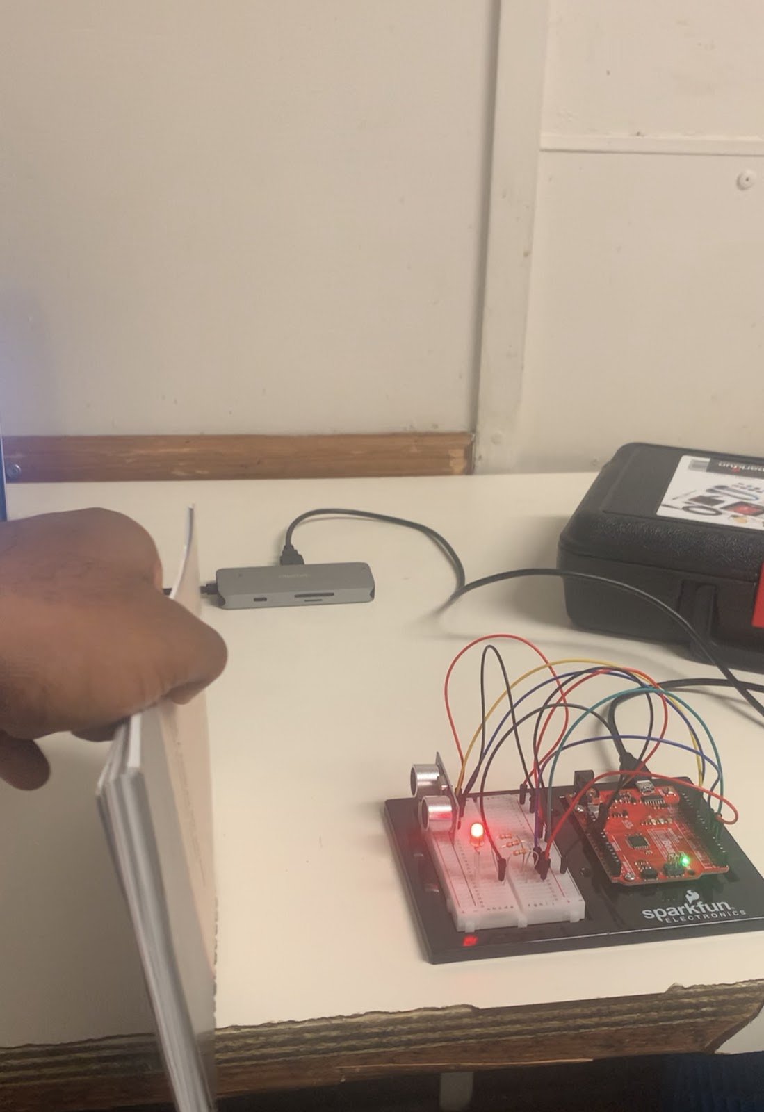
I recently had the opportunity to work on Circuit 3B, which involved using an ultrasonic distance sensor. This component, similar to sonar, sends out sound waves and measures the time it takes for them to bounce off an object and return, allowing it to calculate distance. It was fascinating to explore its applications, including obstacle avoidance in robotics.
Here are some key takeaways from this project:
New Component: Ultrasonic Distance Sensor
The ultrasonic distance sensor used in this circuit operates by sending out bursts of ultrasonic sound at a frequency of 40kHz and then timing how long it takes for the echo to return. It's a bit like echolocation, just like bats or dolphins use. This sensor provides a reliable way to measure distance.
Datasheets
Working with electronics often involves consulting datasheets. In this project, we needed to calculate distance based on the time sound waves travel. The datasheet for the distance sensor contains essential information, including the formula to interpret distance from time measurements.
Else If Statement
To determine the color of an RGB LED based on the measured distance, we used an "else if" statement. It allows us to handle multiple conditions sequentially. For instance, if the distance is less than 10 inches, the LED turns red; if it's between 10 and 20 inches, it turns yellow; otherwise, it's green. This statement is handy for handling various scenarios.
Hardware Hookup
Connecting the components correctly was crucial. The ultrasonic distance sensor has specific pin functions: VCC (power), Trig (trigger), Echo (echo signal), and GND (ground). Following the provided Fritzing diagram ensured that everything was connected properly.
For my setup:
I powered the sensor with 5V.
I connected the trigger and echo pins to specific digital pins on the Arduino.
The RGB LED was connected to digital pins for individual color control.
Coding and Behavior
The Arduino code was essential in making the RGB LED respond to changes in distance. The code continuously measured the distance using the ultrasonic sensor. Depending on the distance value, it adjusted the LED's color. The closer an object, the redder the LED became; at medium distances, it turned yellow, and for farther distances, it turned green.
What I Observed
With the program running, I tested the circuit by moving objects closer and farther from the ultrasonic sensor. It was captivating to witness the RGB LED change colors in real-time, responding to the distance of the objects. This simple setup could have various applications, from indicating proximity to objects to creating interactive installations.
This project provided hands-on experience with sensors and their practical applications in robotics and automation. It's amazing how technology can replicate natural phenomena like echolocation to measure distance accurately. Overall, Circuit 3B was an engaging and educational experience in the world of sensors and Arduino programming.
Motion Alarm
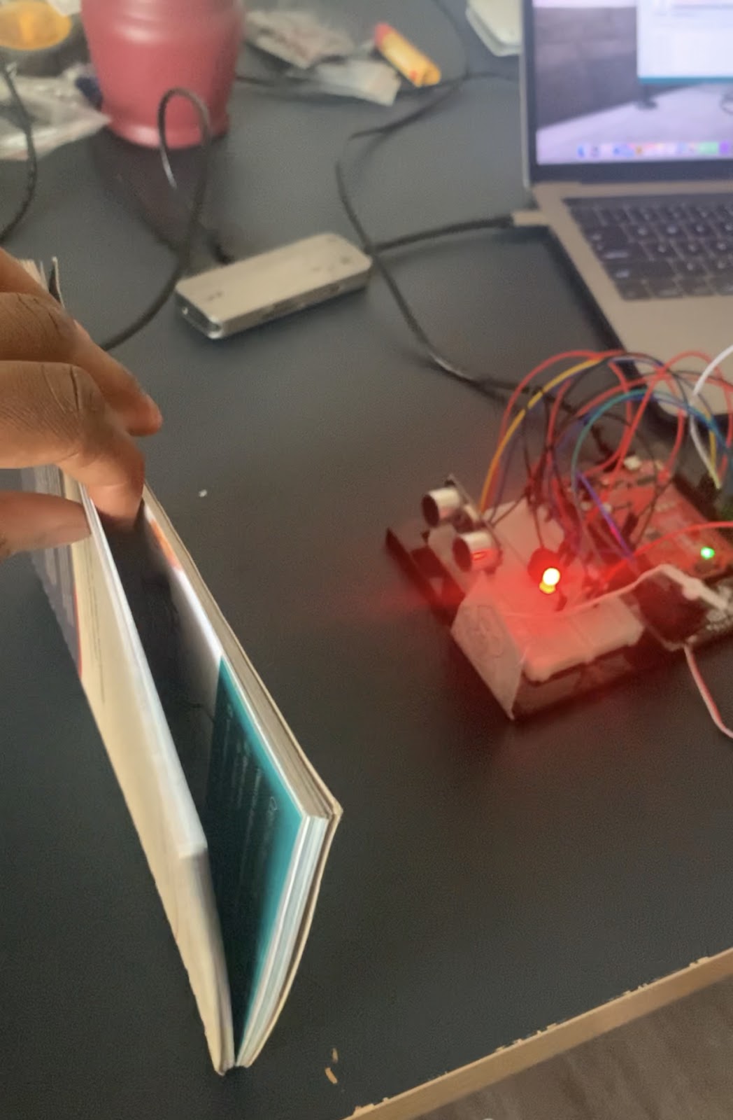
Circuit 3C: Motion Alarm
I had an exciting time working on Circuit 3C, which took our previous distance sensor project to a whole new level. In this project, we used an ultrasonic distance sensor, combined with a servo motor, to create a motion alarm system. The idea was to scare away an unwanted intruder, in this case, my hypothetical prowling cat, by combining light, sound, and motion.
Here's a rundown of what I learned and experienced during this project:
New Component: Servo Motor
The introduction of the servo motor added a new layer of interactivity to the project. Servo motors are versatile components that can be precisely controlled to rotate to specific angles. In this case, we used it to create a pop-up mechanism to animate our alarm.
Getting Creative With Mechanisms
To animate our alarm, we had to get creative with how we attached objects to the servo. This involved using materials like tape, hot glue, paper clips, and linkage rods to create a moving pop-up. It was an excellent opportunity to explore the mechanical aspects of electronics and how to translate servo motion into real-world actions.
Hardware Hookup
The hardware setup included connecting the servo to the RedBoard and attaching the servo mount. We used needle-nose pliers to bend a paperclip into a linkage rod that connected the servo to a menacing cat pop-up. This pop-up was placed under the breadboard baseplate and attached using tape. It was a fascinating combination of electronics and physical mechanisms.
Coding and Behavior
The Arduino code played a critical role in controlling the behavior of our motion alarm. It continuously measured the distance using the ultrasonic sensor, and based on that distance, it determined the color of the RGB LED, which served as a visual indicator. When an object came close (within 10 inches), the LED turned red, and the servo motor started to rotate back and forth, making the pop-up move. Simultaneously, a buzzer emitted a sound to further enhance the alarm effect.
What I Observed
With the program running, I tested the circuit by moving objects closer to the ultrasonic sensor. It was captivating to see how the RGB LED responded, turning red when an object was near. The servo motor's motion added an element of surprise, and the buzzer's sound complemented the alarm system.
This project sparked my imagination, as it could be adapted for various applications beyond just deterring a cat. It could serve as a room alarm, an automated pop-up story, an automatic treat dispenser, or anything else one could dream up. It showcased how electronics and mechanics could be combined to create interactive and practical solutions.
Circuit 3C was a fantastic learning experience that expanded my understanding of servo motors and their applications. It was a delightful mix of creativity and technology, and it encouraged me to explore further possibilities for combining electronics and mechanical elements in future projects.
LCD “Hello World”
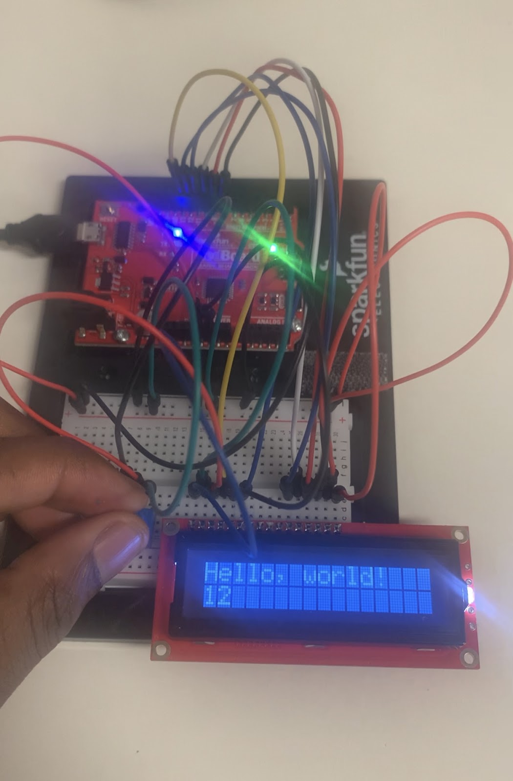
Circuit 4A: LCD "Hello, World!"
I was excited to dive into Circuit 4A, where we got to work with a Liquid Crystal Display (LCD) to print the famous "Hello, world!" message. This circuit introduced me to the world of character LCDs, which are perfect for displaying text and data. Here's my experience with this project:
New Component: Character LCD
The star of this circuit was the character LCD. These displays are fantastic for showing text and basic characters, making them ideal for various applications like clocks, thermometers, and information displays. Understanding how to control and interact with this component opened up a world of possibilities for me.
Contrast Adjustment
One of the key things I learned was how to adjust the contrast of the LCD. Pin 3 on the LCD controlled the contrast and brightness, and we used a potentiometer to adjust it. Rotating the potentiometer helped me find the right contrast level, ensuring that the text displayed correctly. This step was crucial because improper contrast adjustment could result in barely visible or completely unreadable characters.
Pixels and Character Space
I also noticed that characters on the LCD were composed of tiny squares called pixels. These pixels make up the character space, and the size of the display is often measured in pixels. It was fascinating to see how characters were constructed from these pixel grids.
Hardware Hookup
The LCD had 16 pins, which could be a bit intimidating at first glance. Thankfully, the Arduino community has developed a library to simplify the interface between software and hardware. We connected the LCD pins to the RedBoard following a specific wiring diagram, making sure to pay attention to the polarized components and their orientations.
Coding and Behavior
The Arduino code was the heart of this project. It included instructions for initializing the LCD, clearing the display, setting the cursor position, and printing text. We used the LiquidCrystal library to control the LCD, which made programming straightforward. The code displayed "Hello, world!" on the top row and counted the number of seconds since the RedBoard was last reset on the bottom row. It was a simple yet effective way to demonstrate the LCD's capabilities.
What I Observed
Once the circuit was set up and the code uploaded, I observed the LCD displaying the "Hello, world!" message on the top row. Below that, a counter displayed the number of seconds that had passed since I reset the RedBoard. Adjusting the potentiometer allowed me to fine-tune the contrast for optimal visibility.
The project was a great introduction to working with character LCDs and provided a foundation for creating more advanced projects that involve text and data display. It also inspired me to think about how such displays could be used in various real-world applications.
This circuit demonstrated the power of combining hardware and software to create something tangible and functional. It was a simple "Hello, world!" message, but it represented the beginning of a journey into LCD displays and the endless possibilities they offer in the world of electronics and programming.
Temperature Sensor

Circuit 4B: Temperature Sensor
Working on Circuit 4B, I had the opportunity to explore the use of a temperature sensor (TMP36) to monitor temperature and display the readings on an LCD screen. Here's a detailed account of my experience:
New Component: TMP36 Temperature Sensor
The star of this circuit was the TMP36 temperature sensor. This small, three-legged component allowed us to measure temperature accurately. One leg connected to 5V, another to ground, and the third provided a voltage output that varied with temperature changes. The key to using this sensor effectively was understanding the algorithms to convert its output voltage into temperature readings in degrees Celsius and Fahrenheit.
Algorithms for Temperature Conversion
This project introduced me to the concept of algorithms in the context of sensor data processing. The TMP36 sensor provided a voltage output that needed to be converted into meaningful temperature values. This involved several mathematical formulas:
The first formula converted the analog reading from the sensor (ranging from 0 to 1023) into a voltage value between 0V and 5V: voltage = analogRead(A0) * 0.004882813. The magic number 0.004882813 was derived from dividing 5V by the number of analog samples (1024).
The second formula transformed this voltage into degrees Celsius: degreesC = (voltage - 0.5) * 100.0. It subtracted 0.5V from the voltage, accounting for a 0.5V offset mentioned in the TMP36 datasheet, and then multiplied by 100.
The third formula converted degrees Celsius into Fahrenheit: degreesF = degreesC * (9.0/5.0) + 32.0. This standard conversion formula turned Celsius into Fahrenheit.
Understanding these algorithms was crucial because they formed the foundation for processing sensor data in many projects involving analog sensors.
Hardware Hookup
The TMP36 temperature sensor was a polarized component, so it could only be inserted in one direction. Paying close attention to the sensor's markings was essential to avoid potential overheating or incorrect readings. The circuit diagram and hookup table provided clear guidance on connecting all the components correctly.
Coding and Behavior
The Arduino code was at the core of this project. It included instructions for reading the analog voltage from the TMP36 sensor, converting it into temperature values, and displaying those values on the LCD screen. The LiquidCrystal library was used to control the LCD, making it easy to print data.
What I Observed
Once the circuit was set up and the code uploaded, the LCD screen displayed temperature readings in degrees Celsius and Fahrenheit. The temperature values updated every second. It was interesting to observe how pressing a finger against the sensor caused the temperature readings to change. This simple experiment highlighted the practical application of sensors in environmental monitoring and data display.
Coding Challenges
This project left room for exploration and experimentation. I could further enhance the project by:
Displaying the temperature in degrees Kelvin, requiring an additional equation for conversion.
Changing the code to display the temperature as a bar graph instead of numeric values.
Replacing the TMP36 with other sensors like a potentiometer or photoresistor and displaying their values.
Adding an RGB LED that changes color based on the temperature, creating a visual indicator of temperature changes.
Troubleshooting
During the project, I encountered a few common issues:
If the sensor felt warm or hot to the touch, it was crucial to double-check the wiring, ensuring that the temperature sensor was connected correctly.
If the temperature values remained unchanged, I could try heating or cooling the sensor with my fingers or an ice pack to see if the values responded. Also, verifying the sensor's wiring was essential.
If no values were displayed on the LCD, adjusting the LCD contrast was recommended to ensure that the text was visible.
Overall, Circuit 4B was a valuable learning experience that combined hardware, algorithms, and coding to create a practical temperature monitoring system. It served as a solid foundation for more complex sensor-based projects in the future.
“DIY Who Am I” Game

Circuit 4C: DIY Who Am I? Game - My Observations
Upon diving into "DIY Who Am I?" game, I noticed its playful adaptation of the popular Hedbanz concept. Holding an LCD screen to the forehead, players guess words based on hints from others. To bring this game to life, the circuitry involves a 4xAA Battery Holder for convenient, portable power.
Button Debounce and Timing Considerations:
The incorporation of button debouncing intrigued me. It's a subtle yet crucial detail. Without it, the fast execution of code might inadvertently skip words. The 500 ms delay at the loop's end effectively prevents this, ensuring a smoother gameplay experience.
Strings and Arrays:
Strings serve as the canvas for displaying words, which are organized into an array. The clever use of pointers in creating arrays of strings caught my eye. This technique, though advanced, elegantly manages word data for the game.
Random Order and Game Flow:
The mechanism to generate a random order for words adds a dynamic twist to each round. The game progresses through 25 rounds, displaying words, initiating countdowns, and reacting to button presses. The transition between rounds, signaled by a brief delay, adds a polished touch.
Hardware Hookup Challenges:
While the hardware hookup seemed straightforward, I recognized the importance of meticulous attention, especially with polarized components. Placing batteries correctly and securing the battery holder demanded precision.
Engaging User Interface:
The LCD screen, with its countdowns and word displays, forms a robust user interface. The game begins with a category prompt and countdown, providing a clear introduction to players.
Code Flexibility and Challenges:
The code’s modularity and well-defined functions struck me. Tweaking the time limit, changing word lists, or altering soundtracks proved intuitive due to well-commented sections. This flexibility encourages experimentation and customization.
Enhancing the Experience:
The inclusion of sound effects, triggered by the buzzer, significantly enhances the gaming experience. The winning and losing tunes, carefully crafted with varied tones, contribute to the overall immersive feel.
Potential for Expansion:
Considering the game's structure, I couldn't help but envision opportunities for expansion. Modifying word categories, integrating additional sound effects, or incorporating multiplayer dynamics could elevate the game further.
Conclusion:
"Circuit 4C: DIY Who Am I? Game" stands out as an engaging project blending hardware and software seamlessly. Its meticulous design, thoughtful considerations for user experience, and adaptability in coding make it a delightful experiment to explore and, perhaps, build upon.
- Motor Basics

November 1, 2023 - 12:03am
Victor Okpube - Circuit 5B: Remote-Controlled Robot - Unleashing Robotic Mobility
November 1, 2023 - 12:08am
Victor Okpube - Circuit 5C: Autonomous Robot
November 1, 2023 - 12:10am
Victor Okpube - Circuit 5C: Autonomous Robot
November 1, 2023 - 12:18am
Victor Okpube