Athabasca University | AU Student/Staff Login | Invited Guest Login

Motor Basics
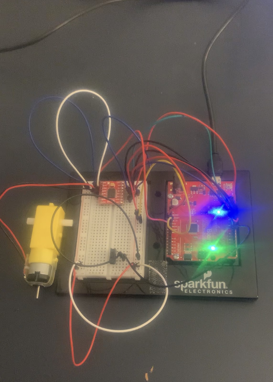
Circuit 5A: Motor Basics - Unleashing Robotic Motion
Embarking on Circuit 5A, I delved into the realm of motor control, a pivotal aspect of robotics. This experiment centered around comprehending the fundamentals of motor operation using a motor driver board. Here's my account of this engaging project:
Objective:
To grasp the essential concepts of motor control and understand the role of a motor driver board in powering and directing motors within a robotics framework.
Key Components:
Motor Control Dynamics:
Motors necessitate a substantial current, requiring a motor controller for efficient operation.
Directly driving motors from digital pins on the RedBoard is impractical, hence the use of a motor driver board.
The inclusion of a gearbox with the DC motor balances speed and strength for versatile robotic movements.
TB6612FNG Motor Driver:
Employing an H-bridge configuration, the motor driver allows seamless control over motor direction.
Commands for motor control, including direction and speed, are conveyed through three essential wires.
Voltage Variability Insight:
The VIN pin's output fluctuates based on the power source, emphasizing the importance of understanding voltage dynamics.
Different power sources, such as USB or a barrel jack, impact the voltage available on the VIN pin.
Integrated Circuits (ICs) and Breakout Boards:
ICs, exemplified by the ATMega328 and TB6612FNG, are fundamental to the RedBoard and motor driver.
Breakout boards streamline IC usage, adapting them for seamless integration into breadboard setups.
Hardware Hookup Challenges:
Attending to polarized components is crucial, ensuring accurate placement on the breadboard.
Deciphering motor driver pins, each with a specific function, plays a pivotal role in influencing motor behavior.
Programming Overview:
Arduino code governs motor behavior based on user input through the Serial Monitor.
The switch acts as an on-off control mechanism, determining whether the motor should initiate rotation.
Coding Challenges:
Switch Direction Control:
Modify the code to make the switch control the motor direction instead of merely turning it on and off.
Button Integration:
Experiment with replacing the switch with a button to activate the motor only when the button is pressed.
Sensor Activation:
Explore code adjustments to activate the motor using a sensor, such as a photoresistor.
Troubleshooting Tips:
Verify motor driver wiring to rectify motor issues, a common challenge due to numerous connections.
Ensure proper Serial Monitor settings for smooth communication and debugging.
Confirm correct switch connections to troubleshoot switch-related problems.
In case of persistent issues, consider the reliability of jumper wires, as bending may lead to wire degradation.
Observations:
Upon successful setup and code upload, the LCD displayed the "Hello, world!" message on the top row.
A seconds counter occupied the bottom row, ticking away since the last RedBoard reset.
Precision in adjusting the potentiometer was essential for achieving optimal contrast and visibility.
Conclusion:
This project laid the foundation for advanced motor control, offering insights into the integration of motors into robotics.
The nuanced understanding of motor drivers, ICs, and coding is critical for constructing responsive robotic systems.
By combining hardware and software effectively, this experiment showcased the tangible and functional outcomes achievable in the realm of robotics and electronics.
- Assignment 2 Weblog

October 2, 2023 - 5:57am
Victor Okpube - Circuit 5B: Remote-Controlled Robot - Unleashing Robotic Mobility

November 1, 2023 - 12:08am
Victor Okpube - Circuit 5C: Autonomous Robot
November 1, 2023 - 12:10am
Victor Okpube - Circuit 5C: Autonomous Robot
November 1, 2023 - 12:18am
Victor Okpube