Athabasca University | AU Student/Staff Login | Invited Guest Login

Torque and Speed in DC Motors

We are asked how we would measure a motor's torque and speed in Matarić's Food for Thoughtsection of chapter 4 (unit 2). There are many approaches to this, from complex empirical measurement and analysis to over-simplified guesswork, the correct approach being the one that results in acceptable system behaviour for a balance of effort, time, and cost.
It’s difficult to measure torque directly, especially during operation, without complex mechanical arrangements. Speed, however, is readily obtainable.
Measuring Motor Speed
Common methods for measuring DC motor angular velocity include using rotary encoders, which may contain optical, electric field, magnetic field, or mechanical sensors; inertial measurement unit (IMU) integrated circuits; back-electromotive force (back-EMF) measurement; and other optical and electromagnetic sensing methods. There are some not-so-common methods that may or may not be effective, but exploring their physics makes for an interesting journey.
Rotary Encoders
These sensors including a moving part, typically a wheel, that attaches to the armature, and a stationary mount. Most types detect angular velocity directly by measuring the absolute position or partial or full revolution frequency, an advantage over all those that require measured and tuned correlation or proportionality constants. The wheel is “encoded” by either changes in conductivity, optical properties (reflectivity, transmittance), magnetic properties, or electric field properties (capacitance). The sensor measures or otherwise reacts to these changes, and may further process the information (analog signal conditioning, digital encoding, etc.). Some motor armatures may have properties inherent to their design that a sensor can pick up, so no extra attachment is necessary. Examples of the conductive version of these are potentiometers (hopefully continuous-rotation!) and rheostats, both of which are now mostly replaced for this type of application by the more dependable optical and magnetic encoders, as the physical connection tends to degrade more quickly. A superficial search on DigiKey.ca for rotary encoders and sensors that could be used as such reveal 8559 products, from $0.72 to $1543.29 each – quite the range.
We can make our own optical rotary encoder with light sources and sensors, and then use either changes in reflectance or transmittance to vary the signals. For example, paint matte black marks on the shaft, position a photodiode such that it only senses a small portion of the shaft at a time (very close, with a mask), then illuminate the area with an LED. As the shaft spins the amount of light detected by the photodiode will vary as the LED light is reflected off the shiny metal parts and off the matt black marks. Similarly, we can set up the light source, sensor, and mask such that light is detected as it shines through the gear teeth or other voids in the gear or wheel body.
We can make our own magnetic rotary encoder with magnetics sources and sensors, and then use either changes in magnetic field strength or magnetic permeability. For example, mount a small Hall sensor near the exposed teeth of a ferromagnetic gear with a permanent magnet on the other side such that when a tooth is closest to the sensor, the average magnetic permeability in that direction is at a maximum, increasing the flux density from the permanent magnet through the sensor. As the gear spins the magnetic field will vary as the teeth approach and recede. Similarly, we can set up the magnetic source and sensor on opposite sides of a ferromagnetic gear or wheel such that the field flows through voids, but is otherwise attenuated.
We can make our own capacitive rotary encoder with high frequency voltage sources and sensors, and then use either changes in voltage or capacitance. For example, mount a near-circular but slightly oval conductive wheel on the shaft encircled by two or more electrically isolated portions of a circular ring, with at least one of them attached to a high frequency source (e.g. 1MHz square wave) and at least one of them attached to a voltage magnitude measuring circuit (e.g. buffer amp followed by envelope demodulator). As the oval wheel spins, the mutual capacitance between it and the encircling rings will vary as the gap between them varies, changing the amplitude of the capacitively coupled voltage signal as it travels from the source to the detector.
The physics employed by rotary encoders can be exploited outside of these packages.
Optical Sensing
Some other interesting optical sensing implementations don’t fit the common definition of a rotary encoder. Lasers can detect material surface speeds using the wave properties of light in several different ways, some of called laser surface velocimeter, laser doppler velocimeter, and velocity interferometer system for any reflector (VISAR). Digital image correlation, comparing successive images of a surface, is used, among numerous other applications, to measure what is called optical flow, and can be employed to determine surface speed of the motor armature. One common example is its use to measure the motion of an optical mouse, a recent product being Logitech’s Darkfield Laser Tracking.
One particularly absurd but possible optical solution is to use optical flow sensors, which measures interval between subsequent laser beams scattering due to single particles naturally present in the atmosphere, on the air spinning around shaft. There is a thin layer of air around the shaft that spins with it, coupled by complex fluid mechanics.
Magnetic Field Sensing
If we can’t get a wire inside or suspect that the output shaft is not in phase with the drive circuitry (for example, when under relatively heavy load), then we can make a loop antenna and put it near the housing, where some field coming from the spinning permanent magnets on the shaft will leak out, giving us a signal in phase with the armature.
Inertial Measurement Unit (IMU) Integrated Circuits
These products typically combine several types of position and acceleration sensors into a single package, sometimes a self-contained PCB or breakout board, with a wide variation in abilities. For measuring angular velocity, and perhaps angle and angular acceleration (and higher order position vector rates of change), we only need an accelerometer or gyroscope, though an inclinometer or magnetometer may be able to do the trick with a fast-enough sensor update and data output rate (bandwidth). Though these products often report angular position, they usually use a method called dead reckoning, which integrates rates of change to calculate change in position, and is susceptible to large errors in our case of more than hundreds of revolutions.
Driver Circuit Sensing
Some of the driver circuit electrical characteristics can be correlated to shaft speed, but not at the extremes of the motor’s operating ranges or when under heavy load. This might be okay if we’re just spinning a light load, like a disk. We can detect changes in magnetic field in a drive coil by wrapping a few turns of wire around one and measuring the induced voltage, getting a signal in phase with the drive signal. Some motors come with this feature built in, called a tap. We may be able to measure frequency of input current spikes, corresponding to driver circuit changing current direction, though only the most basic motor drivers would allow these spikes.
One characteristic comes with the advantage of correlating directly to shaft speed, regardless of operating conditions: back-electromotive force (back-EMF). This is the voltage induced in the drive coils by the spinning magnets on the shaft, countering the input drive voltage. We normally can’t measure it because we’re driving the circuit with a higher voltage to keep the motor going. We can, however, pause for a short time and peek at it’s value. Back-EMF relates linearly to shaft angular speed through some proportionality constant. Back-EMF is also what limits our type of motor’s top speed, when this countering voltage nearly equals and cancels out the drive voltage. This idea lets us estimate the proportionality constant using a given motor’s maximum speed and drive voltage.
For our motor and the datasheet values (3.0 V, 6600 rpm), this gives 4.3 mV/rad/s. Other, more complex options related to back-EMF include measuring its variation frequency; linking a small, unregulated generator (or motor) to the shaft to generate a different EMF (different proportionality constant) without pausing the input; and extracting the back-EMF information from a mixed input PWM and back-EMF signal using signal processing techniques (DSP, analog filtering, etc.).
Vibration Sensing
No armature or shaft is perfectly balanced or has a perfectly smooth surface. The system will tend to vibrate at a frequency related to its spin rate. We can measure this frequency and correlate it to spin rate. A ‘quick and dirty’ method of measuring vibration frequency is to analyze the sound it makes. One could increase the vibration by adding an off-centre weight to the axis.
A force-sensitive probe could also be touched directly on the shaft (perhaps two on opposite sides to cancel out off-axis loading) to measure either vibration frequency or, especially with a particularly well-balanced system and sensitive probe, shaft surface irregularities.
Measuring Motor Output Torque
Torque is the twisting force, called a moment by engineers. A permanent magnet DC motor, like the M260 that we have in our SparkFun Inventor’s Kit (SIK), makes torque by pushing an electrically generated magnetic field around the drive coils against the permanent magnetic fields of the magnets attached to the shaft. Though the concept is simple enough, figuring out how much torque is produced from such an interaction reveals a myriad of unknown variables. As with angular velocity, the driver circuit electrical characteristics can be correlated to torque, but the correlation is difficult to determine analytically. Empirical measurements are the way to go, keeping in mind the mathematical model of the correlation these measurements are meant to fit.
Do you need to know your motor’s torque, though? What are you trying to do? What do you need to move? It is often enough to know that the motor has more than enough power to get the work done, and ignore the details. Indeed, getting bogged down in theoretical details can be the downfall of a project. For example, if you want your robot to use a motor to drive a wheeled axle, you could determine the friction ranges and mechanical linkage relationships of all the moving parts and compare it to the theoretical output torque ranges, but that would take days. Better to just pop in whatever motor you have and use your human fuzzy logic to estimate how its power fit the purpose of the robot. If it’s not enough, order a motor larger than the one you have by whatever fraction you think is necessary. As when planning any step or any part of your system, one must ask the question: is it required to accomplish the goals?
There are, of course, many cases where a few or more than a few calculations are warranted and required. In order of designer effort, which balances time, complexity, and cost, these are the steps in which one can approach the muddy topic.
1. Rough Estimate of Output Torque
Every complex operation starts with an estimate. In our case, we can guess what the some power conversion efficiency from the input electrical power to the output mechanical power.
The motor states its unloaded max speed to be 6600 rpm, with a voltage and current range of 1.0 V to 3.0 V and 110 mA to 800 mA, respectively. In the middle of its operating range the motor will be at 3300 rpm, and we’ll assume the input voltage and current are likewise in the middle of their ranges: 2.0 V and 455 mA, or 910 mW input power. In rotational systems, power is the product of torque and angular velocity. For an efficiency range of 60% to 80%, torque ranges from 1.6 mN·m to 2.1 mN·m[TL3] . If your robot and motor drive circuitry performs well with this range as the peak torque, then you are done – no more calculations necessary. Keep in mind that we’re assuming a lot, including operating in the middle of all ranges, so ensure your gizmo doesn’t need to be outside of these assumptions for anything critical, and that it doesn’t need all the output torque. (I would go with 40% to 60% for most operations, and no more than 80% for the most strenuous, just to make sure it doesn’t stall.)
2. Approximate Average Input Current and Motor Load
Motors can draw a lot of current, especially when they first turn on and under heavy load. Drive circuitry should be designed to handle this, and to do that we’ll need to know the current characteristics. We already know the peak current for the SIK M260 from its datasheet: 800mA. If your motor doesn’t have this number, it’s easy to measure by either locking the rotor, applying the minimum voltage, and measuring the locked rotor current; or by measuring the motor input resistance, which would be the resistance of the wire wrapped around the coils, and figuring it out from there. (Measuring resistance might be the only practical way to do it, as some motors, internal circuitry, measurement instruments, and armature fixtures can be damaged by applying maximum current with a locked rotor.)
We may need to predict more than the maximum current (and power) draw. To get any more information, we’ll have to measure angular velocity, as discussed above under Measuring Motor Speed. This has the added benefit of giving us a relative indication of torque or motor load, as it is directly related to input current and speed.
Keep in mind that the shaft likely will not spin below some minimum torque, as there is some friction to overcome, which translates to some minimum motor load or input current.
3. Do you really need to measure torque?
At this point you probably have everything you need: an estimate for input current, output torque, and some way of measuring speed. These numbers could be used in a motor control technique, given some consideration for propagation of estimation inaccuracies and measurement errors. Maybe it’s not good enough, though. The motor control may not perform as well as required despite efforts to quell the aforementioned effects, or, for some other reason, your system requires more precise values.
There are two ways to approach this: directly measure the output torque, or compare the electrical characteristics (and shaft speed) to device behaviour, or both. As always, there are several more steps, each yielding numbers that are less precise than the next, but that may be sufficient for our purposes.
4. Direct Measurement of Only Locked Rotor Torque (One-Time Measurement)
We could put our motor into a test mount and lock the rotor, as mentioned for measuring the locked rotor current, and take a single measurement of our motor’s output torque. “To every action there is always opposed an equal reaction”, so they say, which means that the shaft torque is opposed by an equal and opposite torque by the motor mounts. There are a number of ways to measure this reaction torque, all involving some sort of scale and moment arm. Once you’ve measured this locked rotor torque, assume that it is zero at full speed and calculate values in between with a linear (decreasing) relationship with RPM.
5. Characterize Electrical Characteristics and Motor Speeds
One can measure a motor’s output speed at multiple operating points, applying a different counter-torque at each, then use the torque to speed relationship to calculate torque. The simplest application of this method is to measure the no-load (no torque) speed and stall speed torque and assume a linear relationship between the two (see above). Another method would assume the motor’s efficiency in converting electrical power to mechanical, measure the electrical power at multiple operating points, then use the current to torque relationship to estimate torque.
A brushless DC motor’s working torque is inversely proportional to angular speed, and input current is directly proportional to motor torque. At a steady angular speed (operating point), motor speed is the sum of whatever is pushing against it, in this case friction and some constant counter-torque. It may also be limited by the controller, which can change the current in the windings only so quickly. Given the complexity introduced by the controller dependency, it makes sense to approximate the relationship between motor torque and other factors instead of determining them analytically (from laws of motion, conservation of momentum, electromagnetics, etc.).
6. Direct Measurement In Real Time (Continuous Measurement)
Force sensors can be placed on the motor mounts in order to measure torque directly.
I have excluded what I wrote under the heading 'Complex Empirical Measurement and Analysis', as it contains many formulas that don't appear correctly on The Landing. It is available in the PDF linked at the end of this post.
Over-Simplified Guesswork: Load or Efficiency
Use Relative Torque or Motor Load [%] Instead
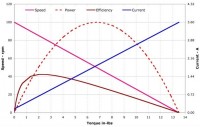
At the other end of the spectrum in systems designer effort, one can simply use average input current or duty cycle as an indicator for torque, assume there is a linear relationship with angular velocity, and calculate approximate motor load (relative torque) instead of absolute torque. The datasheet for the M260 motor from SparkFun shows that the no-load operating point, where torque is zero, is at 110mA and about 6600rpm, and the locked-rotor current, where torque is at a maximum, is 800mA (0 rpm).
Assume Power Conversion Efficiency
A quick and dirty method for estimating torque is to assume some power conversion efficiency from the input electrical power to the output mechanical power.
The motor states its unloaded max speed to be 6600 rpm, driven by 110 mA at 1 V, or 110 mW input power. In the middle of its operating range the motor will be at 3300 rpm, driven by about 455 mA and 2 V, or 910 mW. In rotational systems, power is the product of torque and angular velocity. For an efficiency range of 60% to 80%, torque ranges from 1.6 mNm to 2.1 mNm.
Direct Measurement Using Second Motor
Our SparkFun Inventor’s Kit happened to have come with two M260 motors. We can connect the output of one to the input of the other, measure the input and output electrical characteristics, then determine power transfer efficiency. The electrical input power of the first motor is transformed into mechanical output, which becomes mechanical input energy for the second motor and is transformed into electrical output power, with a power loss or efficiency loss at each transformation.
Assuming the two motor efficiencies are the same and reciprocal, meaning the same in each direction between mechanical and electrical (they probably aren’t), we can drag the equation for efficiency out. We can then relate either input or output power of this arrangement to calculate the torque on the shaft. This can be written with respect to input and output powers.
torque = sqrt( power_in,1 * power_out,2 ) / rotational_speed
Output power should be measured with a matched load, or the unbalanced load should be taken into consideration in the final calculation. (Matched loads receive maximum power from generator: 50%.)
The above was originally written in MS Word with plenty of equations, and includes the section under the heading Complex Empirical Measurement and Analysis. It is available here: http://tyblu.ca/misc/COMP444/blog/blog-post-20170901/COMP444_torque.pdf.
- Assignment 0
July 3, 2024 - 12:47am
Yingjie Huang - Circuit 5B: Remote-Controlled Robot - Unleashing Robotic Mobility

November 1, 2023 - 12:08am
Victor Okpube - Unit 3 & 4
October 14, 2024 - 3:36pm
Yiming Zang - Unit 2 Learning Diary
August 17, 2024 - 11:30pm
Celine Grasdal
Comments
I made a few measurements here: