Athabasca University | AU Student/Staff Login | Invited Guest Login

A Shoddy Robotic Arm

The Instructor's Notebook asks us to design and program (though not necessarily construct) a robotic arm with a working elbow, wrist and end effector.
Design Question
How many motors, and of what type, would you require to make a fully functional robotic arm that had a working elbow, wrist and end affector (i.e. a simple clamp)? What components would you add if you wanted the clamp to be able to tell how hard it was grabbing an object such as an egg (i.e. to avoid crushing it)? Discuss your design in your weblog in detail, especially describing the choice of motor for each joint, the degrees of freedom and the range of motion.
A simple robot arm with an elbow, wrist, and a clamp needs at least 1 motor, preferably a servo-type, for each controlled degree of freedom. In our case, this means 3 servos for each part to move independently and in only a single dimension or path. If you want more degrees of freedom – giving the wrist rotation and tilt, for example – then you need more motors. Complex paths can be constructed that move the robot parts in more than one dimension, but without additional affectors this path is still considered as a single degree of freedom. For example, a robotic wrist can be constructed without a motor that keeps it level in all arm positions. This may seem to be an additional degree of freedom, but the wrist is not actually free to move in any other path. (My project robot arm uses this technique – see below.)


One of the first design limits to look at is the primary arm torque: how much does the arm need to lift, and how far away? This goes a long way towards telling you what type of arm to make and the required motor size to move it. Here's the static torque (moment) analysis for a generic robotic arm: https://i.imgur.com/OYzYE18.jpg.


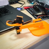
I designed the proposed elbow-wrist-clamp device in Autodesk Fusion 360. (A couple renders are above.) The approximate weight of each part was estimated using the 3D printing program Simplify3D. The maximum torque due to just the assembly weights, with a 10 cm main arm, is about 0.003 Newton-meters or 4.22 oz.-in. The tiny servo in the SparkFun Inventor’s Kit can do 20.8 oz.-in. with 6 V, meaning there are 16.58 oz.-in. left over for friction and other calculation inaccuracies, and the load. Adding 50% to 4.22 oz.-in. for the inaccuracies, giving 6.33 oz.-in., and taking away 25% of the stated maximum servo torque to account for circuit and servo idealities, giving 15.6 oz.-in., leaves 9.3 oz.-in. for the load. The clamp radius from the main arm servo can be up to 140 mm, meaning that the 9.3 oz.-in. available torque can lift up to 48 g. These calculations can be done backwards, starting with the intended load, to impact the strength of servo, driver voltage, arm length, material considerations, and other factors.
The chosen servo has a range of motion limited to about 160°, the joints themselves have mechanical and practical limits. These limits were simulated with the design program, showing that the parts did not interfere with each other and the ranges were practical for their purposes. The main arm joint was allowed to move a full 180°, making the servo the limiter; the wrist articulated laterally (this was done to move it in a different plane than the elbow – a real application may find it more practical to articulate a wrist vertically) through 150°, 75° to each side; the clamp servo only moved 45°, as it did not need to open any wider than a certain point and was restricted by its construction. (None of the parts were designed with a goal in mind other than to show basic operation.)


The end manipulator, the clamp, needs information about it’s grip – force feedback – if it is to grab an object like an egg. The clamp exerts force on the egg, and the egg exerts a reactive force on the clamp. Sensing this reactive force can be done by monitoring the amount of power (current) the clamp servo is using and correlating this with previously measured force data, by placing a purpose-built sensor on the clamp pads to measure the forces, or by changing the mechanics of the clamp such that a sensor can be integrated into its construction. For brittle objects like eggs, it would be a good idea to make the clamp pads soft so that the exerted forces are spread out, without pressure spikes due to surface irregularities.
Programming and Circuit Task
Since we don’t have all the hardware to build a robotic arm, imagine you have been given the task of creating the elbow joint. Select the appropriate motor for this task, and then create a program and circuit using your Arduino which can demonstrate your motor performing the correct elbow movement. It may help if you tape an object such as a popsicle stick, drinking straw, or long skinny piece of paper to your motor to demonstrate the movement of the lower portion of the arm under control of your program. Your program should take as input a number of degrees to move the elbow from an arbitrary starting position. For example, if you choose ‘fully straight’ as the starting position, this will be designated 0 degrees (start). The arm could then bend about 170 degrees, indicating ‘fully bent’.
I’ve been working on a robotic arm for the course project and recently completed a quick-and-dirty program that does exactly as the Programming and Circuit Task requests. It is a bit more sophisticated, but not by much: it controls 4 servos by index number; limits input angles such that it does not put itself in a bad state (hitting itself, the wrist could over-extend, a joint may not bend past certain points, etc.); and has a simple acceleration-limiting algorithm to prevent it from damaging itself when given large angular changes. A snippet of the console is [here], and images of the related robotic states are below.
![[here]](https://i.imgur.com/goQ1vFx.png)


Movement demo of the arm described in the Design Question on YouTube: https://goo.gl/nAQfuk.
Program is on GitHub.com [here]: demo_just_get_it_working.ino.
- Assignment 2 Weblog

October 2, 2023 - 5:57am
Victor Okpube - Circuit 5C: Autonomous Robot

November 1, 2023 - 12:18am
Victor Okpube - Motor Basics
November 1, 2023 - 12:03am
Victor Okpube - Circuit 5B: Remote-Controlled Robot - Unleashing Robotic Mobility
November 1, 2023 - 12:08am
Victor Okpube
Comments
Wow! Awesome robotic arm! Please share your background with 3d printing and design software. What advice would you give a Newby to 3d printing and software? Where did you print the arm? How did you make the joints in 3d design software? Great work.
- Susanne C
Hey Susanne -- thanks! I've been messing around with 3D printing for a few years, and have tried out a few design programs (and other related software). My current favourite is Autodesk Fusion 360. It's free for those that make less than $100k USD per year ("hobbyists and students"), and could be used professionally. It also has a 6-axis CAM package, some simulation capabilities, and a few more tricks. For those new to 3D printing, I'd say jump right into Fusion 360 tutorials, and, if you have your own printer, spend $149 USD on Simplify3D for the best overall experience with slicers, and check out their 3D printing tips and tutorials here: https://www.simplify3d.com/support/.