Athabasca University | AU Student/Staff Login | Invited Guest Login

Generating Robotic Arm Working Ranges

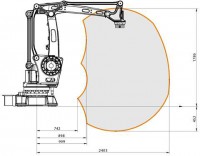
Robotic effectors do work within some space in the real world, and it's a good idea to know exactly what this range is. Working ranges for an arm are well defined, displayed as cross-sectional areas normally from the top-down ("birds-eye view") and from the side for traditional turret-mounted machines. The graphic at the top is from ABB Robotics' IRB460, a "high-speed end-of-line palletizing and bag palletizing" robotic arm upon which my own project is based.
To help create this graphic I used Fusion360 to generate cross-sectional drawings, then imported everything to Photoshop for accurate positioning.
You would think that it would be simpler to position the model in its various configurations in Fusion360, but it proved difficult enough to warrant abandoning that approach. The model I created uses rotating joints between not only the structural pieces but also the ball-bearings, resulting in dozens of joints each with their own set of limits. It works well for checking clearances between parts and verifying operation, but the angles cannot be easily driven to specific independent values. In the future, I will not create rotating joints between the ball bearings and their mating parts, instead using a rigid joint to simply position the part, and creating the moving joints directly between the mating parts. This approach would give me a chance of keeping the motion constraints manageable.
Individual part cross-sections were generated with Fusion360's 2D drawing capabilities, output as a PDF, imported to Inkscape, cleaned up, output as SVG, then imported to Photoshop for positioning. The animation module was used to explode the model parts for drawing without affecting the working model. (Drawings can be generated from the model or animation modules.) I didn't need to export the video, but I love these kind of animations, so take a peek (below):

[Here] is a link to the Fusion360 drawing PDF output. It is not a complete drawing as it is not meant to be used as such. Inkscape is another graphic tool that is fantastic with vector data like PDF and SVG files. I used it to separate the components and make little SVG files for each. These were then popped into Photoshop. Photoshop makes everything easy, including my tasks: position each component into those configurations that clearly show the maximum extents of the device's range. With the Free Transform tool you can set the pivot point to be one of the axes, then rotate components are they would with the real model.
Although I had all of the components and all configurations displayed to make the range areas, I hid most of them to reduce clutter in the final graphic. Only those pieces essential for understanding what's going on were kept. All small mechanical links were removed and most end-effector configurations. I think it would have looked a bit better if there were even fewer pieces, removing some of the boom arms; if the details in the turrent were removed; and if a few links were added back in where they did not clutter the rest to show how the arms were attached.
The end-effector gripper can be mounted in one of 6 configurations, angling the plane from +30° to -120° from horizontal in 30° increments, each with a different cross-sectional working area (range). Instead of creating a separate graphic for each configuration, the practical choice if this were technical documentation for a commercial product, I colour-coded the different ranges to correspond to an End-Effector Configuration Legend. In my opinion, this not only clarified the intent of the graphic but also made it look great, adding a tasteful splash of colour.

Although there are several improvements I'd like to make, it more than serves its purpose as a non-technical but still informative graphic. Let me know what you think! Here's the Photoshop file, if you're curious: [18676 KB PSD file link].
- Circuit 5B: Remote-Controlled Robot - Unleashing Robotic Mobility

November 1, 2023 - 12:08am
Victor Okpube - Circuit 5C: Autonomous Robot
November 1, 2023 - 12:10am
Victor Okpube - Assignment 2 Weblog

October 2, 2023 - 5:57am
Victor Okpube - Circuit 5C: Autonomous Robot
November 1, 2023 - 12:18am
Victor Okpube
Comments
Wow. How did you get so skilled in graphics, Tyler? Was it part of an engineering education? I wonder if I could import parts from Tinkercad into Photoshop. And what made that awesome animation? Fusion360? Nice work.
Hi Tyler. How many degrees of freedom does your robotic arm have? Thank you.
Hey, thanks. I've picked up on graphics by fiddling with it over the past decade, a photograhy hobby, and a bit of perfectionism. Fusion360 did the animation. It's actually not great at doing animations, but it does do the 'explode' bit well. The arm has 3 DOFs, 4 if including the claw.