Athabasca University | AU Student/Staff Login | Invited Guest Login

Project Proposal: Automatic Object Relocation

Project Proposal
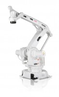
For the COMP444 course project, I would like to make a robotic arm that automatically moves small objects from one location to another, controlled by the SparkFun RedBoard (Arduino). The arm will be based off of the EEZYbotARM MK2 by Carlo Franciscone, which is in turn based off of the ABB IRB 460, an industrial palletizing robot. All structural parts will be 3D printed in PLA. Fasteners, actuators, sensors, and other components will be purchased on eBay.ca, Amazon.ca, DigiKey.ca, and at local hardware stores. It will exchange the EEZYbotARM’s claw with a larger aluminum one that accommodates a more powerful servo. All four of the 3-wire servos will be modified to include a position sensing wire. Two Lynxmotion FSR-01 force sensors will be attached to the claw for grip feedback. An HC-SR04 sonar distance sensor will be suspended near the claw to provide object detection and positioning. The servos will have a separate power supply from the Arduino.
Possible Difficulties
- The EEZYbotARM MK2 will be 3D-printed and contains many joints with little consideration of friction. It may need to be redesigned to reduce friction.
- Near its maximum reach, the arm may not be able to lift the metal claw, the claw’s servo, and all of the mentioned sensors attached near the end-effector. I will install the most powerful servo available for the designed form factor to reduce this chance. Calculations confirm that the arm will be able to lift itself and a small load at its maximum radius, but all factors have not been taken into account. There may be more friction than anticipated, the servos may not perform to their stated specifications, and there may be unaccounted load sources (like wiring).
- The sonar distance sensor may not be able to detect small objects. It is normally used for larger surface areas. A scanning algorithm may be developed to reduce the sensor scanning area. Otherwise, a different type of sensor may be required, such as an infrared or laser distance sensor, or clever use of a whisker bump switch. It may be prudent to use a set initial position, if time becomes a factor.
- The force sensors may not provide high enough resolution for the relatively small forces generated by the claw, causing the claw servo to draw maximum power and possibly damage itself. This can be avoided with input current sensing, but more sensitive force sensors would be a more complete solution. (Over-current protection is always a good idea.)

Note
Construction of the proposed arm is currently nearly complete. Remaining steps include attaching and enabling the sensors, and programming the device. It did need re-engineering to reduce friction, detailed in these two blog posts: Manipulator Arm Modifications, Manipulator Arm Modifications – Success!- Circuit 5B: Remote-Controlled Robot - Unleashing Robotic Mobility

November 1, 2023 - 12:08am
Victor Okpube - Circuit 5C: Autonomous Robot
November 1, 2023 - 12:10am
Victor Okpube - Assignment 2 Weblog

October 2, 2023 - 5:57am
Victor Okpube - Circuit 5C: Autonomous Robot
November 1, 2023 - 12:18am
Victor Okpube
Comments
Great robot, Tyler, and thanks for all your feedback. Would you please tip me off on how to make an arm joint? What bolt or whatever would allow for the rotation? Thank you
Hey Susanne. Most of the joints in this arm have ball bearings, but that's not really required if you're not worried about friction.
For small loads you can just attach an arm directly to a motor, servo, or stepper, without giving it additional axial support (like a bolt). My Shoddy Robotic Arm does this. All of the hobby servos and stepper motors I've seen come with a way to attach some standard piece to their shaft, and it's usually a tight fit. They often come with an assortment of these connector pieces, called "horns". (I got some aluminum ones for some of my joints, and they grip even better, giving a rigid connection.)
For a bit more rigidity you can introduce some axial support. There are two ways of doing this: keep the driving force (torque) directly in line with the axis as it was without axial support (above) and put an axle on the other side of the joint; or put the axle right through the joint and move the driving force elsewhere, which may necessitate at least one more joint to transfer the torque. (You'll have to figure out a way to attach the motor to the arm while going around the axle.)
Generally, larger size joints and axles mean less wobble (relative to their size) but more friction. There is a sweet spot for each application for allowable wobble: too much or too little causes the joint to bind. It's pretty obvious what will work when making a joint -- just do what looks right. The largest bolts I used for the above were M6 (6mm diameter). Most of the joints have M4 or M3 bolts with a lock/nylon nut on the end, so it doesn't have to be tightened against something and potentially binding it, and a few metal washers sprinkled around to take advantage of their lower friction coefficients compared to 3D-printed plastic. (The washers keep the plastic parts from touching.)
Great feedback, thanks. I needed to look up axle, but now I get the gist. I wonder if I could take the axle from servo motor and attach it to a bracket that attaches to an arm. Thanks very much.
Great idea Tyler! One thought on the weight of the effector when fully extended - perhaps see if you can design some type of counterweight to balance things when fully extended?
Although the servos have proven to be sufficient to move the whole contraption with a moderate load, I have ended up adding something like a counterweight. The end-effector is kept level with respect to the ground regardless of arm angle via mechanical connections, but this connection only works below a certain angle. If the jib arm (2nd arm; I call it the boom) is lifted too high, the end-effector can 'flip' down, putting the whole thing in a bad state. This isn't an issue during operation, as the arm is meant to stay near the ground, but it sometimes did this when the Arduino was reset, as the driving pulse delays (usually incorrectly called PWM) are not controlled. To counter this I strung a bungee between the end-effector and a point above the boom, ensuring that it came taut when the boom was near the top of its range. I like the way it behaves and how simple it was to integrate it into the model. If I get the time, I may follow this approach to give the arm servos some extra lifting power. It'd kinda be like how a work lamp keeps its position using springs.
An image render is below. The new pieces are in red. The bungee is a continuous loop like a belt, going between the circular shivs:
Printing preview:
Finished:
Video of build process and before and after comparison: https://goo.gl/cN1GtE
Nice work Tyler. It looks like you've got multiple oscilloscopes in the background. Nice setup.
What gives your newly attached piece its weight other than the plastic? And what size drill bit did you use to drill the holes to connect it to the arm?
Thanks! The end-effector has a metal claw, servo, and sonar sensor. Joint friction adds a bit of load, too. It was a tiny drill bit -- must have been 1/16" -- just for a pilot hole.
Wow, you actually 3d printed some of the components. Very impressive! Way to set the bar. In your "about me" section, you mentioned that you have taken electrical engineering courses. Did you take the NAIT Diploma program or?
Cheers
Hey Shawn, thanks! I was in the EE Nanotech program at the UofA for many years (2004-2011'ish), but I didn't graduate. They didn't do 3D printing or robotics then, but it did give me taste enough in related fields to continue related hobby work.
I survived first year engineering and decided to finish my degree online with comp sci because it seems more flexible :)